← Back to catalogue
Spectacle Blind · Class 600 Family: Spectacle BlindsReference: Spectacle blind · Class 600Standard: ASME B16.48
Dimensions according to ASME B16.48-2020. All dimensional values are in mm . DN and NPS are nominal designations; NPS retains its inch designation.
RF · Female RTJ · Male RTJ
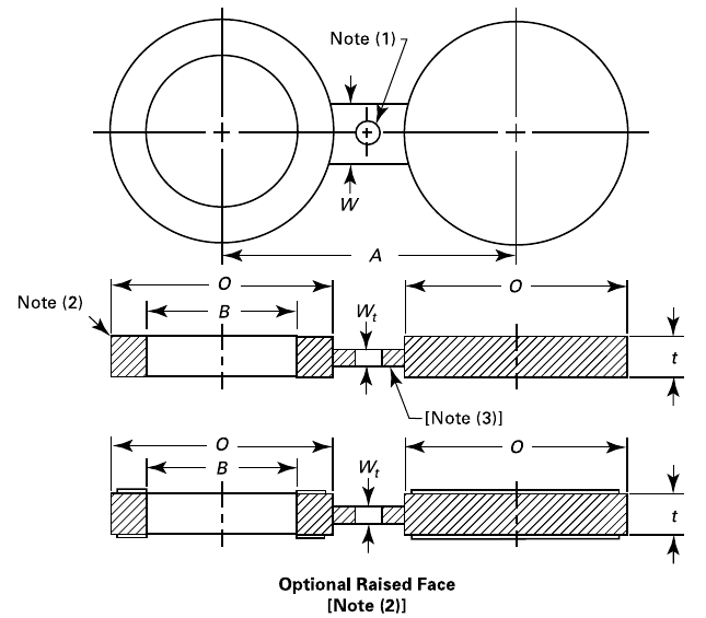
RF · For raised face flanges Dimensioned drawing Click the drawing to enlarge. B: inside diameter · O: outside diameter · A: centre-to-centre distance · t: thickness · W: bridge width.
The clearance hole, where required, shall have the same diameter as the flange bolt hole and shall not interfere with the bolts. Bridge thickness Wt is determined in accordance with Section 4.1 of the standard. The raised face shown is optional; see Section 4.3.1.
Class 600 · RF Dimensions in mm. DN / NPS nominal sizes in bold.
DN NPS B · Bore Ø O · Outside Ø A · Centre to centre t · Thickness W · Bridge 15 1/2″ 16 51 65 6,4 38 20 3/4″ 21 64 80 6,4 38 25 1″ 27 70 90 6,4 57 32 1 1/4″ 37 79 100 9,7 57 40 1 1/2″ 43 92 115 9,7 67 50 2″ 55 108 125 9,7 57 65 2 1/2″ 67 127 150 12,7 67 80 3″ 83 146 170 12,7 67 90 3 1/2″ 96 159 185 15,7 76 100 4″ 108 191 215 15,7 76 125 5″ 135 238 265 19,1 86 150 6″ 162 264 290 22,4 86 200 8″ 212 318 350 28,4 95 250 10″ 265 397 430 35,1 105 300 12″ 315 454 490 41,1 105 350 14″ 346 489 525 44,5 114 400 16″ 397 562 605 50,8 124 450 18″ 448 610 655 53,8 133 500 20″ 497 679 725 63,5 133 600 24″ 597 787 840 73,2 152
DN 15 · NPS 1/2″ DN 15
NPS 1/2″
B · Bore Ø 16
O · Outside Ø 51
A · Centre to centre 65
t · Thickness 6,4
W · Bridge 38
DN 20 · NPS 3/4″ DN 20
NPS 3/4″
B · Bore Ø 21
O · Outside Ø 64
A · Centre to centre 80
t · Thickness 6,4
W · Bridge 38
DN 25 · NPS 1″ DN 25
NPS 1″
B · Bore Ø 27
O · Outside Ø 70
A · Centre to centre 90
t · Thickness 6,4
W · Bridge 57
DN 32 · NPS 1 1/4″ DN 32
NPS 1 1/4″
B · Bore Ø 37
O · Outside Ø 79
A · Centre to centre 100
t · Thickness 9,7
W · Bridge 57
DN 40 · NPS 1 1/2″ DN 40
NPS 1 1/2″
B · Bore Ø 43
O · Outside Ø 92
A · Centre to centre 115
t · Thickness 9,7
W · Bridge 67
DN 50 · NPS 2″ DN 50
NPS 2″
B · Bore Ø 55
O · Outside Ø 108
A · Centre to centre 125
t · Thickness 9,7
W · Bridge 57
DN 65 · NPS 2 1/2″ DN 65
NPS 2 1/2″
B · Bore Ø 67
O · Outside Ø 127
A · Centre to centre 150
t · Thickness 12,7
W · Bridge 67
DN 80 · NPS 3″ DN 80
NPS 3″
B · Bore Ø 83
O · Outside Ø 146
A · Centre to centre 170
t · Thickness 12,7
W · Bridge 67
DN 90 · NPS 3 1/2″ DN 90
NPS 3 1/2″
B · Bore Ø 96
O · Outside Ø 159
A · Centre to centre 185
t · Thickness 15,7
W · Bridge 76
DN 100 · NPS 4″ DN 100
NPS 4″
B · Bore Ø 108
O · Outside Ø 191
A · Centre to centre 215
t · Thickness 15,7
W · Bridge 76
DN 125 · NPS 5″ DN 125
NPS 5″
B · Bore Ø 135
O · Outside Ø 238
A · Centre to centre 265
t · Thickness 19,1
W · Bridge 86
DN 150 · NPS 6″ DN 150
NPS 6″
B · Bore Ø 162
O · Outside Ø 264
A · Centre to centre 290
t · Thickness 22,4
W · Bridge 86
DN 200 · NPS 8″ DN 200
NPS 8″
B · Bore Ø 212
O · Outside Ø 318
A · Centre to centre 350
t · Thickness 28,4
W · Bridge 95
DN 250 · NPS 10″ DN 250
NPS 10″
B · Bore Ø 265
O · Outside Ø 397
A · Centre to centre 430
t · Thickness 35,1
W · Bridge 105
DN 300 · NPS 12″ DN 300
NPS 12″
B · Bore Ø 315
O · Outside Ø 454
A · Centre to centre 490
t · Thickness 41,1
W · Bridge 105
DN 350 · NPS 14″ DN 350
NPS 14″
B · Bore Ø 346
O · Outside Ø 489
A · Centre to centre 525
t · Thickness 44,5
W · Bridge 114
DN 400 · NPS 16″ DN 400
NPS 16″
B · Bore Ø 397
O · Outside Ø 562
A · Centre to centre 605
t · Thickness 50,8
W · Bridge 124
DN 450 · NPS 18″ DN 450
NPS 18″
B · Bore Ø 448
O · Outside Ø 610
A · Centre to centre 655
t · Thickness 53,8
W · Bridge 133
DN 500 · NPS 20″ DN 500
NPS 20″
B · Bore Ø 497
O · Outside Ø 679
A · Centre to centre 725
t · Thickness 63,5
W · Bridge 133
DN 600 · NPS 24″ DN 600
NPS 24″
B · Bore Ø 597
O · Outside Ø 787
A · Centre to centre 840
t · Thickness 73,2
W · Bridge 152
↑ Back to the top of this data sheet
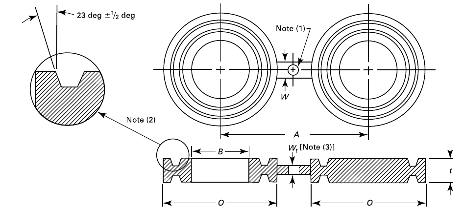
Female RTJ · Ring joint groove Dimensioned drawing Click the drawing to enlarge. B: inside diameter · O: outside diameter · A: centre-to-centre distance · t: thickness · W: bridge width.
The clearance hole, where required, shall have the same diameter as the flange bolt hole and shall not interfere with the bolts. Bridge thickness Wt is determined in accordance with Section 4.1 of the standard. The RTJ groove is dimensioned according to ASME B16.5.
Class 600 · FEMALE RTJ Dimensions in mm. DN / NPS nominal sizes in bold.
DN NPS B · Bore Ø O · Outside Ø A · Centre to centre t · Thickness W · Bridge 15 1/2″ 21 51 65 19,1 38 20 3/4″ 27 64 80 22,4 45 25 1″ 34 70 90 22,4 51 32 1 1/4″ 42 79 100 22,4 51 40 1 1/2″ 48 90 115 22,4 57 50 2″ 61 108 125 28,4 57 65 2 1/2″ 73 127 150 31,8 57 80 3″ 89 146 170 31,8 57 90 3 1/2″ 102 159 185 35,1 64 100 4″ 114 175 215 35,1 64 125 5″ 141 210 265 38,1 70 150 6″ 168 241 290 44,5 83 200 8″ 219 302 350 50,8 95 250 10″ 273 356 430 57,2 102 300 12″ 324 413 490 63,5 121 350 14″ 356 457 525 66,5 127 400 16″ 406 508 605 73,2 127 450 18″ 457 575 655 79,2 127 500 20″ 508 635 725 88,9 127 600 24″ 610 749 840 104,6 152
DN 15 · NPS 1/2″ DN 15
NPS 1/2″
B · Bore Ø 21
O · Outside Ø 51
A · Centre to centre 65
t · Thickness 19,1
W · Bridge 38
DN 20 · NPS 3/4″ DN 20
NPS 3/4″
B · Bore Ø 27
O · Outside Ø 64
A · Centre to centre 80
t · Thickness 22,4
W · Bridge 45
DN 25 · NPS 1″ DN 25
NPS 1″
B · Bore Ø 34
O · Outside Ø 70
A · Centre to centre 90
t · Thickness 22,4
W · Bridge 51
DN 32 · NPS 1 1/4″ DN 32
NPS 1 1/4″
B · Bore Ø 42
O · Outside Ø 79
A · Centre to centre 100
t · Thickness 22,4
W · Bridge 51
DN 40 · NPS 1 1/2″ DN 40
NPS 1 1/2″
B · Bore Ø 48
O · Outside Ø 90
A · Centre to centre 115
t · Thickness 22,4
W · Bridge 57
DN 50 · NPS 2″ DN 50
NPS 2″
B · Bore Ø 61
O · Outside Ø 108
A · Centre to centre 125
t · Thickness 28,4
W · Bridge 57
DN 65 · NPS 2 1/2″ DN 65
NPS 2 1/2″
B · Bore Ø 73
O · Outside Ø 127
A · Centre to centre 150
t · Thickness 31,8
W · Bridge 57
DN 80 · NPS 3″ DN 80
NPS 3″
B · Bore Ø 89
O · Outside Ø 146
A · Centre to centre 170
t · Thickness 31,8
W · Bridge 57
DN 90 · NPS 3 1/2″ DN 90
NPS 3 1/2″
B · Bore Ø 102
O · Outside Ø 159
A · Centre to centre 185
t · Thickness 35,1
W · Bridge 64
DN 100 · NPS 4″ DN 100
NPS 4″
B · Bore Ø 114
O · Outside Ø 175
A · Centre to centre 215
t · Thickness 35,1
W · Bridge 64
DN 125 · NPS 5″ DN 125
NPS 5″
B · Bore Ø 141
O · Outside Ø 210
A · Centre to centre 265
t · Thickness 38,1
W · Bridge 70
DN 150 · NPS 6″ DN 150
NPS 6″
B · Bore Ø 168
O · Outside Ø 241
A · Centre to centre 290
t · Thickness 44,5
W · Bridge 83
DN 200 · NPS 8″ DN 200
NPS 8″
B · Bore Ø 219
O · Outside Ø 302
A · Centre to centre 350
t · Thickness 50,8
W · Bridge 95
DN 250 · NPS 10″ DN 250
NPS 10″
B · Bore Ø 273
O · Outside Ø 356
A · Centre to centre 430
t · Thickness 57,2
W · Bridge 102
DN 300 · NPS 12″ DN 300
NPS 12″
B · Bore Ø 324
O · Outside Ø 413
A · Centre to centre 490
t · Thickness 63,5
W · Bridge 121
DN 350 · NPS 14″ DN 350
NPS 14″
B · Bore Ø 356
O · Outside Ø 457
A · Centre to centre 525
t · Thickness 66,5
W · Bridge 127
DN 400 · NPS 16″ DN 400
NPS 16″
B · Bore Ø 406
O · Outside Ø 508
A · Centre to centre 605
t · Thickness 73,2
W · Bridge 127
DN 450 · NPS 18″ DN 450
NPS 18″
B · Bore Ø 457
O · Outside Ø 575
A · Centre to centre 655
t · Thickness 79,2
W · Bridge 127
DN 500 · NPS 20″ DN 500
NPS 20″
B · Bore Ø 508
O · Outside Ø 635
A · Centre to centre 725
t · Thickness 88,9
W · Bridge 127
DN 600 · NPS 24″ DN 600
NPS 24″
B · Bore Ø 610
O · Outside Ø 749
A · Centre to centre 840
t · Thickness 104,6
W · Bridge 152
↑ Back to the top of this data sheet
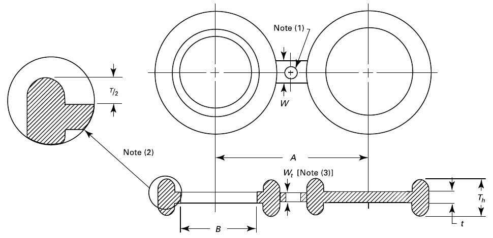
Male RTJ · Integral ring Dimensioned drawing Click the drawing to enlarge. B: inside diameter · A: centre-to-centre distance · t: thickness · W: bridge width.
The clearance hole, where required, shall have the same diameter as the flange bolt hole and shall not interfere with the bolts. Bridge thickness Wt is determined in accordance with Section 4.1 of the standard. Oval or octagonal rings are permitted. Their dimensions correspond to ASME B16.20, with Th = T + t; T is the ring height.
Class 600 · MALE RTJ Dimensions in mm. DN / NPS nominal sizes in bold.
DN NPS B · Bore Ø A · Centre to centre t · Thickness W · Bridge 15 1/2″ 21 65 6,4 38 20 3/4″ 27 80 9,7 45 25 1″ 34 90 9,7 51 32 1 1/4″ 42 100 9,7 57 40 1 1/2″ 48 115 9,7 57 50 2″ 61 125 12,7 51 65 2 1/2″ 73 150 15,7 57 80 3″ 89 170 15,7 67 90 3 1/2″ 102 180 19,1 67 100 4″ 114 215 19,1 73 125 5″ 141 265 22,4 73 150 6″ 168 290 28,4 73 200 8″ 219 350 35,1 83 250 10″ 273 430 41,1 121 300 12″ 324 490 47,8 121 350 14″ 356 525 50,8 121 400 16″ 406 605 57,2 127 450 18″ 457 650 63,5 133 500 20″ 508 720 69,9 127 600 24″ 610 840 82,6 152
DN 15 · NPS 1/2″ DN 15
NPS 1/2″
B · Bore Ø 21
A · Centre to centre 65
t · Thickness 6,4
W · Bridge 38
DN 20 · NPS 3/4″ DN 20
NPS 3/4″
B · Bore Ø 27
A · Centre to centre 80
t · Thickness 9,7
W · Bridge 45
DN 25 · NPS 1″ DN 25
NPS 1″
B · Bore Ø 34
A · Centre to centre 90
t · Thickness 9,7
W · Bridge 51
DN 32 · NPS 1 1/4″ DN 32
NPS 1 1/4″
B · Bore Ø 42
A · Centre to centre 100
t · Thickness 9,7
W · Bridge 57
DN 40 · NPS 1 1/2″ DN 40
NPS 1 1/2″
B · Bore Ø 48
A · Centre to centre 115
t · Thickness 9,7
W · Bridge 57
DN 50 · NPS 2″ DN 50
NPS 2″
B · Bore Ø 61
A · Centre to centre 125
t · Thickness 12,7
W · Bridge 51
DN 65 · NPS 2 1/2″ DN 65
NPS 2 1/2″
B · Bore Ø 73
A · Centre to centre 150
t · Thickness 15,7
W · Bridge 57
DN 80 · NPS 3″ DN 80
NPS 3″
B · Bore Ø 89
A · Centre to centre 170
t · Thickness 15,7
W · Bridge 67
DN 90 · NPS 3 1/2″ DN 90
NPS 3 1/2″
B · Bore Ø 102
A · Centre to centre 180
t · Thickness 19,1
W · Bridge 67
DN 100 · NPS 4″ DN 100
NPS 4″
B · Bore Ø 114
A · Centre to centre 215
t · Thickness 19,1
W · Bridge 73
DN 125 · NPS 5″ DN 125
NPS 5″
B · Bore Ø 141
A · Centre to centre 265
t · Thickness 22,4
W · Bridge 73
DN 150 · NPS 6″ DN 150
NPS 6″
B · Bore Ø 168
A · Centre to centre 290
t · Thickness 28,4
W · Bridge 73
DN 200 · NPS 8″ DN 200
NPS 8″
B · Bore Ø 219
A · Centre to centre 350
t · Thickness 35,1
W · Bridge 83
DN 250 · NPS 10″ DN 250
NPS 10″
B · Bore Ø 273
A · Centre to centre 430
t · Thickness 41,1
W · Bridge 121
DN 300 · NPS 12″ DN 300
NPS 12″
B · Bore Ø 324
A · Centre to centre 490
t · Thickness 47,8
W · Bridge 121
DN 350 · NPS 14″ DN 350
NPS 14″
B · Bore Ø 356
A · Centre to centre 525
t · Thickness 50,8
W · Bridge 121
DN 400 · NPS 16″ DN 400
NPS 16″
B · Bore Ø 406
A · Centre to centre 605
t · Thickness 57,2
W · Bridge 127
DN 450 · NPS 18″ DN 450
NPS 18″
B · Bore Ø 457
A · Centre to centre 650
t · Thickness 63,5
W · Bridge 133
DN 500 · NPS 20″ DN 500
NPS 20″
B · Bore Ø 508
A · Centre to centre 720
t · Thickness 69,9
W · Bridge 127
DN 600 · NPS 24″ DN 600
NPS 24″
B · Bore Ø 610
A · Centre to centre 840
t · Thickness 82,6
W · Bridge 152
↑ Back to the top of this data sheet
Let’s discuss your next project Tell us the standard, dimensions, material and quantity you require.
TOBER SL C/ Brincadero, nº 25
TOBER SL · Legal notice · Privacy · Cookies